Switch Topology
Changes
To
announce a change in the active network topology, switches send a TCN BPDU.
Table 2.10 shows the format of these messages.
Table
2-10 Topology Change Notification BPDU Message
Content
Field
Description
|
Number
of Bytes
|
Protocol ID
(always 0)
|
2
|
Version (always
0)
|
1
|
Message Type
(Configuration or TCN BPDU)
|
1
|
A
topology change occurs when a switch either moves a port into the Forwarding
state or moves a port from the Forwarding or Learning states into the Blocking
state. In other words, a port on an active switch comes up or goes down. The
switch sends a TCN BPDU out its root port so that, ultimately, the root bridge
receives news of the topology change. Notice that the TCN BPDU carries no data
about the change but informs recipients only that a change has occurred. Also notice that the switch will not send
TCN BPDUs if the port has been configured with PortFast enabled.
The
switch continues sending TCN BPDUs every
hello time interval until it gets an acknowledgment from its upstream neighbor.
As the upstream neighbors receive the TCN BPDU, they propagate it on toward the
root bridge and send their own acknowledgments. When the root bridge receives
the TCN BPDU, it also sends out an acknowledgment. However, the root bridge
sets the Topology Change flag in its Configuration BPDU, which is relayed to
every other bridge in the network. This is done to signal the topology change
and cause all other switches to shorten their switch table aging times from the
default (300 seconds) to the forward delay value (default 15 seconds).
This
condition causes the learned locations of MAC addresses to be flushed out much sooner
than they normally would, easing the bridge table corruption that might occur because
of the change in topology. However, any stations that are actively
communicating during this time are kept in the bridge table. This condition
lasts for the sum of the forward delay and the max age (default 15 + 20 seconds).
The
theory behind topology changes is fairly straightforward, but it is often
difficult to grasp how a working network behaves during a change. For example,
suppose that you have a Layer 2 network (think of a single VLAN or a single instance
of STP) that is stable and loop free. If a switch uplink suddenly failed or a
new uplink was added, how would the various switches in the network react?
Would users all over the network lose connectivity while the STP “recomputes”
or reconverges?
Examples
of different types of topology changes are presented in the following sections,
along with the sequence of STP events. Each type has a different cause and a
different effect. To provide continuity as the STP concepts are presented, the
same network previously shown in Figures 2.3 through 2.5 is used in each of
these examples.
Direct Topology Changes
A direct topology
change is one that can be detected on a switch interface. For example, if a
trunk link suddenly goes down, the switch on each end of the link can
immediately detect a link failure. The absence of that link changes the
bridging topology, so other switches should be notified.
Figure 2.11 shows
a network that has converged into a stable STP topology. The VLAN is forwarding
on all trunk links except port gi1/0/2 on Switch C, where it is in the Blocking
state.
This network has
just suffered a link failure between Switch A and Switch C. The sequence of
events unfolds as follows:
1.Switch C detects a link down on its port gi1/0/1;
Switch A detects a link down on its port gi1/0/2.
2.Switch C removes
the previous “best” BPDU it had received from the root over port gi1/0/1. Port
gi1/0/1 is now down so that BPDU is no longer valid. Normally, Switch C would
try to send a TCN message out its root port, to reach the root bridge. Here,
the root port is broken, so that is not possible. Without an advanced feature
such as STP UplinkFast, Switch C is not yet aware that another path exists to
the root. Also, Switch A is aware of the link down condition on its own port
gi1/0/2. It normally would try to send a TCN message out its root port to reach
the root bridge. Here, Switch A is the root, so that is not really necessary.
3.The root bridge, Switch A, sends a Configuration BPDU
with the TCN bit set out its port gi1/0/1. This is received and relayed by each
switch along the way, informing each one of the topology change.
4.Switches B and C
receive the TCN message. The only reaction these switches take is to shorten
their bridging table aging times to the forward delay time. At this point, they
do not know how the topology has changed; they only know to force fairly recent
bridging table entries to age out.
5.Switch C basically
just sits and waits to hear from the root bridge again. The Configuration BPDU
TCN message is received on port gi1/0/2, which was previously in the Blocking
state. This BPDU becomes the “best” one received from the root, so port gi1/0/2
becomes the new root port. Switch C now can
progress port gi1/0/2 from Blocking through the Listening, Learning, and
Forwarding states.
Figure
2.11 Effects of a Direct Topology Change
As
a result of a direct link failure, the topology has changed and STP has
converged again. Notice that only Switch C has undergone any real effects from
the failure. Switches A and B heard the news of the topology change but did not
have to move any links through the STP states. In other words, the whole
network did not go through a massive STP reconvergence.
The
total time that users on Switch C lost connectivity was roughly the time that
port gi1/0/2 spent in the Listening and Learning states. With the default STP
timers, this amounts to about two times the forward delay period (15 seconds),
or 30 seconds total.
Indirect Topology Changes
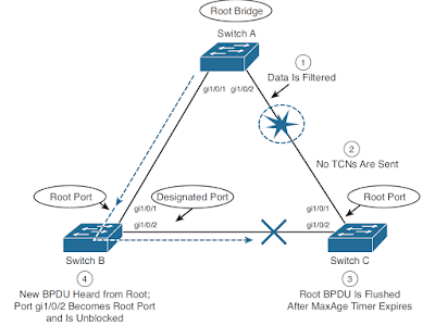
Figure 2.12 shows
the same network as Figure 2.11, but this time the link failure indirectly involves
Switches A and C. The link status at each switch stays up, but something between
them has failed or is filtering traffic. This could be another device, such as
a service provider’s switch, a firewall, and so on. As a result, no data
(including BPDUs) can pass between those switches.
Figure
2.12 Effects of an Indirect Topology Change
STP
can detect and recover from indirect failures, thanks to timer mechanisms. The sequence
of events unfolds as follows:
1.
Switches A and C both show a link up condition; data
begins to be filtered elsewhere on the link.
2.
No link failure is detected, so no TCN messages are
sent.
3.
Switch C already has stored the “best” BPDU it had
received from the root over port gi1/0/1. No further BPDUs are received from
the root over that port. After the Max Age timer expires, no other BPDU is
available to refresh the “best” entry, so it is flushed. Switch C now must wait
to hear from the Root again on any of its ports.
4.
The next Configuration BPDU from the root is heard on
Switch C port gi1/0/2. This BPDU becomes the new “best” entry, and port gi1/0/2
becomes the root port. Now the port is progressed from Blocking through the
Listening, Learning, and finally Forwarding states.
As
a result of the indirect link failure, the topology does not change
immediately. The absence of BPDUs from the root causes Switch C to take some
action. Because this type of failure relies on STP timer activity, it generally
takes longer to detect and mitigate.
In
this example, the total time that users on Switch C lost connectivity was
roughly the time until the max age timer expired (20 seconds), plus the time
until the next Configuration BPDU was received (2 seconds) on port gi1/0/2,
plus the time that port gi1/0/2 spent in the Listening (15 seconds) and
Learning (15 seconds) states. In other words, 52 seconds elapse if the default
timer values are used.
Insignificant Topology Changes
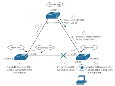
Figure 2.13 shows
the same network topology as Figure 2.11 and Figure 2.12, with the addition of
a user PC on access layer switch Switch C. The user’s switch port, gi1/0/33/,
is just another link as far as the switch is concerned. If the link status goes
up or down, the switch must view that as a topology change and inform the root
bridge.
Figure 2.13 Effects of an Insignificant Topology
Change
Obviously,
user ports are expected to go up and down as the users reboot their machines, turn
them on and off as they go to and from work, and so on. Regardless, TCN
messages are sent by the switch, just as if a trunk link between switches had
changed state. To see what effect this has on the STP topology and the network,
consider the following sequence of events:
1.
The PC on switch port gi1/0/33 is turned off. The
switch detects the link status going down.
2.
Switch C begins sending TCN BPDUs toward the root,
over its root port (gi1/0/1).
3.
The root sends a TCN acknowledgment back to Switch C
and then sends a Configuration BPDU with the TCN bit set to all downstream
switches. This is done to inform every switch of a topology change somewhere in
the network.
4.
The TCN flag is received from the root, and both
Switches B and C shorten their bridge table aging times. This causes recently
idle entries to be flushed, leaving only the actively transmitting stations in
the table. The aging time stays short for the duration of the Forward Delay and
Max Age timers.
Notice
that this type of topology change is mostly cosmetic. No actual topology change
occurred because none of the switches had to change port states to reach the
root bridge. Instead, powering off the PC caused all the switches to age out
entries from their bridge or CAM tables much sooner than normal.
At
first, this does not seem like a major problem because the PC link state
affects only the “newness” of the CAM table contents. If CAM table entries are
flushed as a result, they probably will be learned again. This becomes a
problem when every user PC is considered. Now every time any PC in the
network powers up or down, every switch in the network must age out CAM
table entries.
Given
enough PCs, the switches could be in a constant state of flushing bridge
tables. Also remember that when a switch does not have a CAM entry for a
destination, the packet must be flooded out all its ports. Flushed tables mean
more unknown unicasts, which mean more broadcasts or flooded packets throughout
the network.
Fortunately,
Catalyst switches have a feature that can designate a port as a special case. You
can enable the STP PortFast feature on a port with a single attached PC. As a
result, TCNs are not sent when the port changes state, and the port is brought
right into the Forwarding state when the link comes up.


No comments:
Post a Comment